Technical overview
Main computer
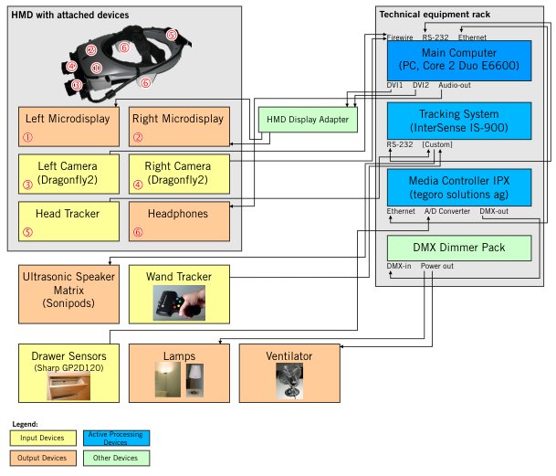
The main computer is the heart of the system, where all inputs (cameras, tracking data, sensors) come together and are processed to generate the visual output as well as audio and signals for controlling the real-world devices. The computer used is a standard PC running Windows XP, with an Intel Core Duo 6600 CPU, 2 GB RAM and an Nvidia EN7900GTX graphics processor. This GPU provides enough power to render the AR scenarios in adequate quality and is equipped with two separate DVI outputs and can thus be used for stereoscopic rendering.
Visual system: head-mounted display (HMD) with camera see-through
To achieve the desired composition of a real-world image overlayed by virtual 3D-objects, we use a display system involving a high-resolution stereo HMD together with a stereoscopic camera setup. This provides the user with a basic, realistic view of the real world, while technically opening the possibility to manipulate the user's view.
The HMD used is the nVisor SX manufactured by NVIS. This HMD has two separately controllable LCOS microdisplays (one per eye), each with a field-of-view of 60° and a resolution of 1280x1024 (SXGA). This HMD has a hard plastic enclosure which allows relatively easy mounting of additional hardware, e.g. cameras and head-tracker. Headphones are also integrated in the casing.
After evaluating various low-cost webcams, we eventually decided to use higher-quality industrial cameras. In the final system, we used two Dragonfly2 cameras manufactured by Point Grey Research with 1/3" CCDs with VGA resolution, together with Fujinon vari-focal lenses with manual zoom, focus and iris. The selected camera/lens combination has several advantages over lower-cost webcams:
- Higher framerates: most webcams only provided 15 fps, and although some devices allowed framerates up to 30 fps, the quality of the images at these framerates was nearly unusable, with much noise and heavy compression artifacts. With the Dragonfly2 cameras we were able to obtain uncompressed RGB24 images in VGA resolution (640x480) at 30 fps. This framerate is necessary to allow for a satisfactory immersive experience.
- Lower latency: for a satisfactory user experience, the latency of the camera see-through system must be kept as low as possible. Using the webcams, the latency was measured to be in the order of 3-5 frames, while with the Dragonfly2 cameras the latency was less than 2 frames.
- Better control over optical characteristics: the possibility to use interchangable lenses allows us to closely match the camera optics to the provided field of view of the HMD.
- Better control over camera parameters: the software drivers of the Dragonfly2 cameras allow more precise control over gain, white balance and other image parameters than most Webcam drivers.
- Better reliability of Firewire vs. USB
To allow monitoring of the user's view, the DVI outputs of the PC are split using active DVI splitters, allowing the image for each eye to be sent to a large LCD screen as well as to the HMD.
3D Software Environment / Rendering Engine
The 3D software environment Virtools was used to build the AR scenarios. This platform provides a sophisticated development environment for interactive 3D content as well as a high quality 3D rendering engine. In the visual programming environment, so-called "building blocks" providing various functionalities can be combined in a drag-and-drop manner and thus used to implement interactivity and manipulate 3D objects. The available building blocks allow complex interactive 3D scenarios to be implemented without low-level coding.
Functionalities which can not be directly implemented in the visual programming environment may be realized either using a built-in scripting engine or by extending the environment by programming plug-ins in C++ using the Virtools SDK.
Tracking system
To accurately superimpose virtually rendered objects onto the real-world camera image, the position and orientation of the cameras must be known and correspond to the position of the virtual camera.
This is achieved by attaching a head-tracking device to the HMD enclosure. The offset between the head-tracker and the cameras is assumed to be constant, so that the position and orientation of the cameras can be easily calculated from the measured position and orientation of the head-tracker. We use an Intersense IS-900 hybrid tracking system which combines ultrasonic time-of-flight measurements with inertial sensor data to provide high accuracy and tracking stability. This system consists of the following components:
- A matrix of ultrasonic speakers which are mounted in a regular pattern on the ceiling of the living room: The positions of these speakers must be accurately measured, as the positions of the tracked devices are calculated using the distances to these speakers.
- The tracked devices contain multiple microphones which receive signals from the ultrasonic speakers, as well as inertial sensors. In our system, two tracked devices are in use: a head-tracker and a handheld tracking device ("wand-tracker").
- A processing unit controls the ultrasonic speakers and filters and processes the received data from the tracked devices. The calculated tracking data (position and orientation) are sent to the main computer via an RS-232 serial connection.
Calibrating the IS-900 tracking system
For the tracking system to be able to provide accurate data, the exact position of each ultrasonic speaker (Sonipod) must be determined. This was achieved with the help of the "Institute for Measurement and Geo-Information, FHNW", who performed the measurements using professional equipment from Leica Geosystems.
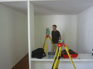
With these measurements, the tracking system can be configured for our set-up. Using a customized VRPN-server the tracking data can be made available in the Virtools environment.
Real-World Interfaces
One goal of the project was to explore possibilities of interactivity between real-world and virtual objects. The following real-world objects are interfaced to the system:
- Two floor lamps and one table lamp in the living room can be switched on and off as well as dimmed by the system
- A ventilator can also be switched on and off with variable speed.
- The four furniture drawers are used as input devices: they are fitted with distance sensors which sense when they are opened.
The real-world interfaces are controlled using a Media Controller IPX by tegoro solutions ag. This is a microcontroller-based device with Ethernet, DMX, serial, analog and digital I/O connections. Custom firmware was developed together with a Virtools plug-in to implement an interface to the main AR engine. The lamps and ventilator are connected to a DMX dimmer pack which is controlled by the Media Controller according to signals received from the main engine. The sensors used in the drawers are Sharp GP2D120 infra-red range sensors which supply an analogue signal to the Media Controller. The analogue inputs are converted to digital values, filtered and sent to the main engine by the Media Controller firmware. A simple UDP/IP protocol is used for communication between the Media Controller and the main engine.
Additional system for recording user sessions
To be able to evaluate users' behavior in the AR scenarios, we wanted to be able to record videos showing the rendered AR view as well as the user's reactions. A separate system with a PC, webcam and DVI frame grabber was built in addition to the main AR system to be able to record these videos of the users' experiences. The rendered 3D scene was captured and combined with images from a camera directed into the room. This recording functionality was implemented using Max/MSP/Jitter.